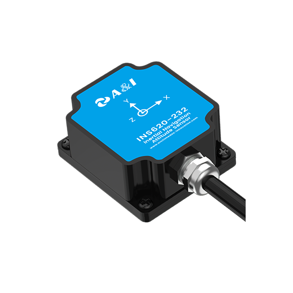
This framework presents a systematic approach to hardware splicing and pinout mapping tailored for modular, high‑rigidity arrays used in precision agriculture. It assumes teams must reconcile mechanical stiffness, repeatable electrical interfaces and field‑grade diagnostics so that nodes integrate cleanly with autonomous systems such as autonomous navigation. The recommendations draw on field lessons from pilot installations in Israel’s Negev desert where modular irrigation and sensing rigs required robust pinout discipline to sustain continuous operation under dust and vibration.
Framework Overview: Layers and Deliverables
The framework divides the work into four concurrent layers: mechanical interface, electrical pinout, interface documentation, and validation tests. Each layer has a clear deliverable: CAD mating detail for the mechanical interface; a pinout table and wiring harness spec for the electrical interface; a versioned connector map as documentation; and a test report capturing continuity, insulation and functional checks. This decomposition creates a reproducible workflow suited to integration with vehicle controllers and edge compute stacks using RTK GNSS and CAN bus telemetry.
Mechanical and Electrical Principles
Begin with the mechanical envelope: define mounting datum surfaces and a single-cycle torque spec for connector retention. Use keyed connectors and blind-mate features where practical to reduce installation error. Electrically, adopt a reserved conductor map: power, chassis ground, signal ground, differential pairs, and low-voltage logic lines (GPIO / I2C) each assigned fixed pin ranges. Insist on shield termination at one point only to avoid ground loops and specify IP ratings for connector mating cycles. These simple constraints reduce ambiguous splices when arrays are expanded or reconfigured in the field.
Pinout Mapping Methodology
Map pinouts with a consistent naming convention: module.function.signal. Create a master CSV and a human‑readable schematic for every revision. Use color-coded sleeving and keyed ferrules on harness ends for technician clarity. For each connector, include: pin, wire gauge, insulation type, intended current, and EMI considerations. Validation proceeds in stages—continuity, insulation resistance, then functional load tests—so that both bench and field faults are isolated before deployment. A small aside—document every ad hoc splice; undocumented changes are the most frequent failure mode in multi‑season systems.
Integration with Autonomous Systems and Compute
When the array interfaces to navigation controllers and edge compute—often a ROS node or a dedicated ai computing platform—define a communication tier that separates deterministic control (CAN bus) from non‑deterministic telemetry (Ethernet). Provide isolated power rails for sensors such as LiDAR to prevent noise coupling into signal lines. Include a service port on every module for firmware access and a standardized boot pin so field updates do not require custom harnesses. These provisions simplify fleet management and remote diagnostics while supporting precise positioning from RTK GNSS.
Common Mistakes and Validation Tests
Common errors repeat: swapped differential pairs, missing shield terminations, incorrect wire gauges at current paths, and failure to test under vibration. Build a concise test matrix for pre‑deployment: continuity table, megohm insulation test, vibration endurance on the connector assembly, and a powered functional test under nominal supply. Use automated test jigs where volume justifies them; otherwise a standardized manual checklist reduces human variability.
Advisory: Three Golden Rules for Selection and Deployment
1. Prioritise mechanical datum and connector keying over marginal cost savings; a consistent physical interface prevents most field errors.
2. Standardise pinout namespaces across the fleet and lock them into version control—change only through approved revision steps.
3. Require a simple, repeatable validation sequence (continuity → insulation → functional) and enforce it at every handover.
These three rules yield measurable improvements: lower mean time to repair, fewer configuration mismatches, and higher first‑pass deployments in harsh terrains. The approach aligns with successful ag‑tech deployments that couple robust hardware with disciplined software stacks—experience that organisations like Archimedes Innovation bring to system-level integration. Final thought — practical discipline beats clever ad hoc fixes every time.