
The problem: uninterrupted power where the grid cannot be trusted
Frequent outages and planned shutoffs create a clear technical mandate: maintain critical loads without any perceptible interruption. For many homeowners this means integrating a robust inverter, battery, and control stack — often paired with a whole house battery backup — so that lights, refrigeration, and medical devices never see a break. The challenge is not merely storage capacity; it is the choreography of grid sensing, inverter switching, and battery management to achieve a zero‑drop transfer.
Core technical elements of a bi‑directional PV inverter hybrid
A reliable zero‑drop system relies on a few distinct pieces working in concert. At the center sits the bi‑directional inverter that can operate as a grid‑tie converter and as an off‑grid inverter, handling power flow both to and from a storage bank. The PV inverter hybrid integrates solar input, the battery management system (BMS), and a fast transfer mechanism. Key terms to know here include state‑of‑charge (SoC) monitoring, grid intertie protocols, and anti‑islanding detection. Each element must be selected to the same performance class; mismatched response times or protective thresholds will defeat seamless transfer.
Control strategies that enable true zero‑drop transfers
Achieving a transition with no interruption requires precise synchronization before any switch occurs. Modern systems use a phase‑locked loop (PLL) and tight voltage/frequency windows to keep the inverter output phase‑aligned with the grid. When loss is detected the hybrid controller executes a handover: inverter output asserts as grid voltage collapses, the transfer relay either remains closed (make before break) or electronic switches take over, and the battery supplies any microscale gap. Some systems employ soft start waveforms and droop control to stabilize islanded operation immediately after transfer.
Common mistakes and practical mitigations
Engineers often underestimate latency and overestimate margin — leading to visible flicker or load trips. Typical errors include undersized inverters, overly conservative SoC thresholds, slow mechanical relays instead of solid‑state switching, and neglect of firmware updates that refine detection algorithms. Commissioning shortcuts are costly; proper timing tests and fault simulations should be mandatory. Calibration of protective settings is not theoretical — it is practical work done at site under load.
Implementation considerations and a real‑world anchor
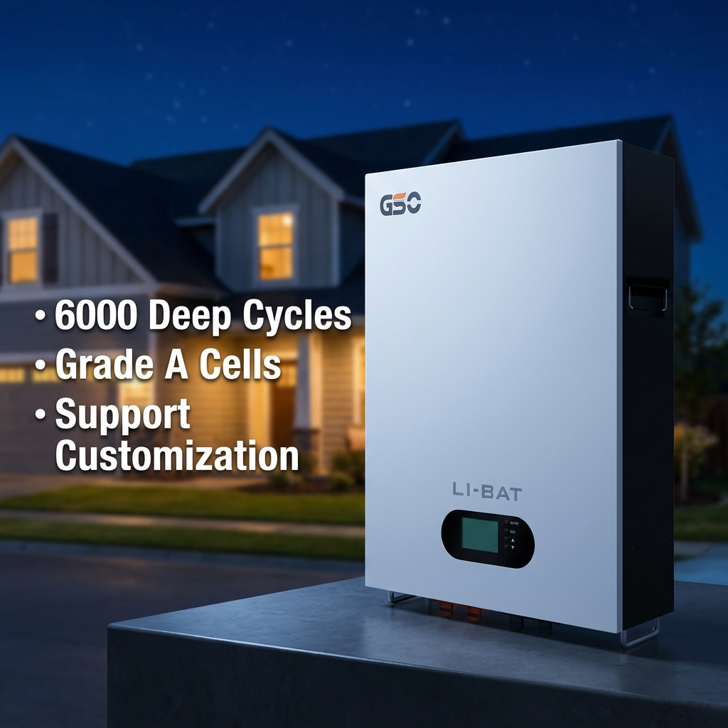
Field experience matters. During repeated Public Safety Power Shutoffs in California, households with well‑commissioned PV hybrids and LiFePO4 storage maintained essential circuits while neighbors cycled on generators or lost refrigeration — a clear demonstration of the architecture in action. Select batteries rated for high cycle life, configure SoC reserves for emergency use, and validate anti‑islanding schemes against regulatory requirements. For many installers the product that balances performance and lifecycle concerns is found alongside a tested whole house battery for solar.
Three critical metrics to evaluate a prospective system
1) Transfer latency: measure end‑to‑end time from grid failure detection to inverter‑supplied load; targets under 10 ms prevent most UPS interruptions. 2) Sustained continuous power rating: ensure inverter and battery together can supply worst‑case simultaneous loads for the desired duration — not just peak pulses. 3) BMS responsiveness and SoC transparency: the system must report accurate SoC and react to conditions (over/under voltage, temperature) without human intervention. These metrics reveal real readiness, and they are measurable during commissioning.
When you put those measures together, you get systems that perform in stress events and day‑to‑day life — which is precisely the value that gsopower brings to design and delivery. —