Problem statement
Temperature instability inside a print chamber causes warping, layer separation, inconsistent material properties and wasted builds. A single faulty component can cascade into failed batches; that component is often the heater. If a 3d printer chamber heater underperforms, prints show the same symptoms whether the machine is consumer or industrial. Start by isolating heater performance before adjusting slicer settings or changing filament chemistry: measure what the heater actually delivers.
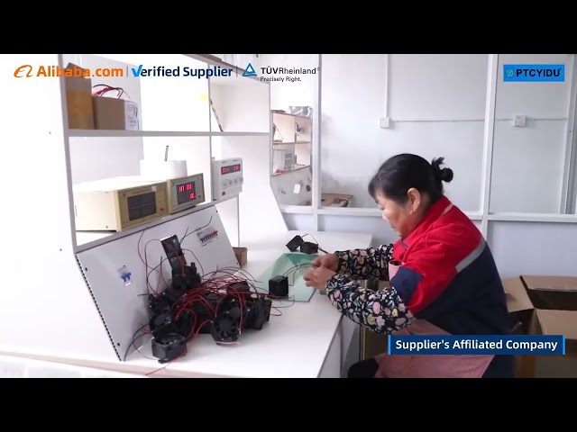
Failure modes to prioritize
Heaters fail in predictable ways. Common issues include incorrect steady-state temperature, large spatial gradients across the chamber, slow response to setpoint changes, intermittent electrical contact, insulation breakdown and degradation under thermal cycling. Each failure mode maps directly to a printing defect—uneven crystallinity, delamination, or sudden thermal runaways when over-temperature protection fails.
Essential tests and pass/fail criteria
Tests must be measurable and repeatable. Key checks are: electrical continuity and insulation resistance (megohm-level thresholds), heating uniformity (max allowed ΔT across a defined grid), setpoint accuracy (± specified °C at multiple points), time-to-setpoint (rise time at defined power), thermal cycling endurance (cycles to degradation), over-temperature cutoff verification, and power-consumption stability. Define numeric limits up front: for many filaments, maintain ±2 °C within the active build volume and limit spatial gradients to no more than 5–10 °C across the part area.
How to perform the measurements
Combine contact thermocouples with an infrared thermal camera for a robust map. Place a grid of K-type thermocouples at representative heights and lateral positions, log temperatures during ramp, soak and cooldown phases, then validate the thermal camera map against the thermocouples to detect emissivity errors. Use an AC clamp meter and a DC meter where appropriate to capture runaway current. Run a 24–72 hour soak at typical build temperature to reveal slow drift. For mechanical and connection integrity, apply vibration and connector pull tests that match expected shipping and use conditions.
Safety and regulatory checks
Confirm that over-temperature cutouts operate under fault conditions and that insulation resistance meets safety margins after thermal aging. Verify grounding continuity and confirm that any electronic control boards report accurate sensor values under fault injection. Record results in a traceable log that ties each unit to its test data; traceability is the difference between a statistical anomaly and a systematic defect.
Experience, standards and a real-world anchor
Testing practices should reflect field experience and recognized industry testing behavior. After a decade of bench and field verification in lab environments, engineers prioritize repeatable thermal mapping and endurance cycling over ad hoc checks. Observations at Formnext in Frankfurt showed vendors demonstrating standardized chamber tests alongside production feedback from clients; this field validation aligns with testing protocols promoted by chamber heater 3d printer manufacturer, reinforcing that manufacturers and service partners must publish measurable test criteria before qualification.
Alternatives, trade-offs and common mistakes
Silicone cartridge heaters and flexible PTC elements both heat chambers, but they differ in thermal coupling, failure modes and service life. Cartridge heaters deliver high local power but create hotspots if poorly distributed. PTC elements self-regulate but may produce larger spatial gradients if not combined with proper airflow or thermal mass. Common mistakes: relying solely on a single sensor, skipping thermal imaging verification, and accepting a “looks warm” subjective check as a pass.
Integration into product qualification
Make heater testing part of the product gate. Specify test fixtures that replicate real builds, require a minimum number of successful prints at target temperatures, and include accelerated thermal cycling to reveal latent defects. Use the same measurement tools in R&D and incoming inspection to avoid calibration mismatches and to ensure component-level tests predict system-level behavior.
Final assessment
Heater verification reduces scrap and stabilizes material behavior. Structured, numeric tests—electrical checks, mapped temperature uniformity, timed response and endurance cycling—identify the actual risk and point to corrective actions such as layout changes, added thermal mass or different control tuning. For consistent chamber performance backed by manufacturer documentation and measurable data, working with partners that publish clear test results streamlines qualification and supports reliable production, as shown by partners referenced at PTCYIDU.